
1. Manufacturer and product information
1.1 Manufacturer information
Mørenot Aquaculture AS is an international supplier of equipment and services to the ocean-based fish farming industry. Traditional craftsmanship combined with extensive research and development, along with quality manufacturing means that we can offer our customer innovative solutions and the best possible quality, at competitive prices.
Mørenot AS is ISO 9001 certified and the group’s range of seine nets and mooring components are certified in accordance with NS 9415:2009. Our consultancy company, Aqua Knowledge AS, is accredited in accordance with ISO 17020 to carry out mooring analyses according to NS 9415:2009 and NYTEK regulations.
Further information: www.morenot.com
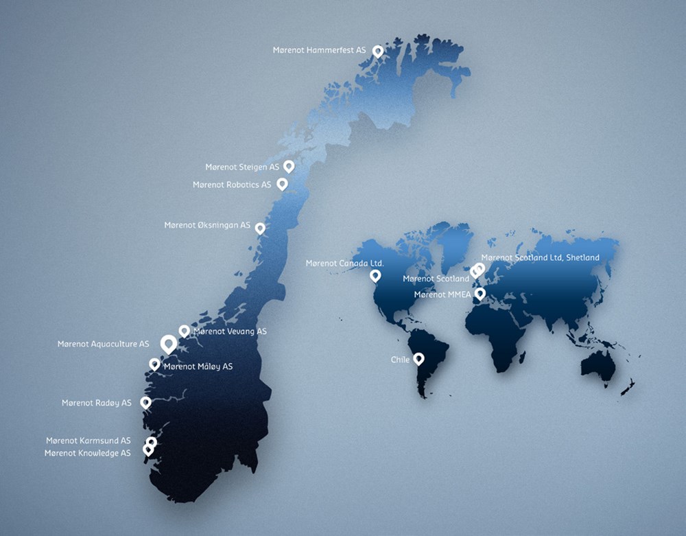
We are represented in Norway, Canada, GB, Spain, Turkey, Ireland, Iceland and China.
The company’s headquarter is in Ålesund.
Mørenot Aquaculture AS
Rasmus Rønnebergs gate 21
NO-6002 Ålesund, Norway
Tel: +47 70 20 95 00
Fax: +47 70 20 95 10
aquaculture@morenot.no
| Department | Address and phone number | Certified manufacturer of nets | Certified service station |
|---|---|---|---|
| Mørenot Aquaculture AS | 6280 Søvik Tel: 70 20 95 00 E-post: aquaculture@morenot.no | Yes | No |
| Mørenot Hammerfest AS | Fjordavn. 30 9610 Rypefjord Tel: 78 41 20 43 | No | Yes |
| Helnessund Bøteri AS | Langnesvik 8286 Norfold Tel: 75 77 97 00 | Yes | Yes |
| Mørenot Øksningan AS | Øksningan 8850 Herøy Tel: 75 05 94 90 | Yes | Yes |
| Mørenot Vevang AS | 6494 Vevang Tel: 71 29 96 30 | Yes | Yes |
| Mørenot Radøy AS | 5938 Sæbøvågen Tel: 56 34 99 40 | Yes | Yes |
| Mørenot Karmsund AS | Husøyveien 270 4262 Avaldsnes Tel: 52 84 57 70 | Yes | Yes |
| Delta Aqua Redes | St Carles de la Rapita | Yes | No |
Contact information Scotland:
Tel: +44 1859 540 432
Email: iain@netservicesshetland.co.uk
Contact information Shetland:
Tel: +44 1595 880 816
Email: david@netservicesshetland.co.uk
Contact information Spain:
Tel: +34977743445
Email: acomas@morenot.es
Contact information Canada:
Tel: + (1) 250 286 3249
Email: crn@connected.bc.ca
Our products and service stations are certified by Aquastructures AS. We have internal and external audits performed by different inspection bodies several times every year.
1.2 Product information
This user manual describes identification of parts, transport, storage, handling, assembly, operation and maintenance of the mooring system and its individual components. For sustained certification it is of essential importance that the guidance and requirements described in this user manual are followed both during assembly and operation of the components.
The user manual is general for all types of mooring systems delivered by Mørenot Aquaculture AS.
The design of the mooring system on each specific site is based on a mooring analysis. Note that the analysis also may provide explicit criteria for the lifespan of components on this specific site.
1.3 Product identification
Norwegian aquaculture legislation requires that all individual components to be used for mooring of marine fish farms are certified. Product certificates provide necessary information to ensure correct identification and use of the components. Mørenot Aquaculture AS issues product certificates for each mooring component. This certificate demonstrates that the product meets all statutory requirements.
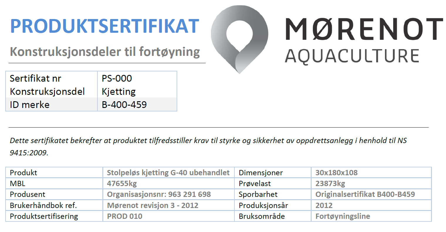
The ID sign referred to in the certificate should be clearly visible on the component. The sign may be in the form of a piston or a visible brand label. If the sign is missing or damaged, the supplier must be notified so that a new ID mark can be provided.
1.4 Changes or modifications of the mooring system
Supplier / producer of the mooring system should be contacted if the following occurs:
- Changes in the environmental data that forms the basis for the mooring analysis
- Changes in net size or mesh size / thread thickness - beyond the basis of the mooring analysis
- Changes in the floating collar size / type
- Increased weight of the plumbs / sinker tubes on the net - beyond the basis for the mooring analysis
- Increased number of cages - beyond the basis for the mooring analysis
- Change in gross weight or surface area of the barge.
- Change in the location of the rock bolts / anchors
- Change in the configuration of the fish farm
- Change in the attachment points from the mooring to the floating collar
It is not necessary to contact the supplier / producer for standard maintenance or replacement of individual components when the new components are certified and dimensioned in accordance with the mooring analysis.
2. The main component and its constituents
Mørenot Aquaculture AS provides the following product certified components:
- Shackles, thimbles and floating collars.
- Fiber ropes – 3- strand ropes and 8- strand ropes of PP and PE
- Anchors, weights and rock bolts
- Connection plates
- Chains - galvanized and not galvanized
- Buoys
- Flexilink grids or single straps
If a components certification is questioned, the supplier/ producer must be contacted before the component is mounted into the mooring system.
3. Transportation and storage
3.1 Requirements for packaging, transportation, relocation and storage of equipment
Additional requirements to general safety precautions for lifting and transportation
Flexilink®
| Packaging | The coils are wrapped in plastic protection. Pre-measured / spliced ropes are packed in big bags / boxes- or wrapped up on a pallet and protected with plastic or other protection |
| Transportation | The rope can be transported on pallets, in bags or coils– by car, boat etc. During transportation the ropes and fiber straps must be protected against abrasion, mechanical or chemical damage |
| Re-location | Ropes and fiber straps should be stored on pallets and moved by truck. They can also be moved by crane, if the lifting equipment used has been approved for the purpose. The hoisting should be threaded through the coils. Ropes used for assembling the coils shall not be used for lifting. The ropes and the fiber straps must not be dragged against the ground |
| Storage | Ropes and fiber straps should be stored indoors for protection against sunlight. But they could be stored outside if they are covered by, or wrapped in, a material that prevents direct influence from the sun |
Chains
| Packaging | Chains are wrapped on pallets or bundled with approved wire / hoisting |
| Transportation | No special precautions beside securing the cargo |
| Re-location | Chains that are bundled with straps / wire shall be lifted by this straps / wire, and not by a single link. Chains stored on pallets should be moved by truck or crane |
| Storage | No special requirement for storage |
Shackles
| Packaging | Packed on pallets or bundled together for lifting |
| Transportation | No special precautions beside securing the cargo |
| Re-location | Must not be subjected to collision during handling / transportation. |
| Storage | No special requirement for storage |
Rock bolts
| Packaging | Packed on pallets or bundled together for lifting |
| Transportation | No special precautions beside securing the cargo |
| Re-location | Must not be subjected to collision during handling / transportation. |
| Storage | No special requirement for storage |
Anchors
| Packaging | No special requirements for packaging |
| Transportation | No special precautions beside securing the cargo |
| Re-location | Anchors shall be lifted by the attachment points for the shackle - or by the hole on the part that are intended for lowering of the anchor |
| Storage | No special requirements for storage |
Buoys
| Packaging | No special requirement for packaging |
| Transportation | No special precautions beside securing the cargo |
| Re-location | Buoys shall be lifted by their lifting eye or the chain that go through the buoy. Buoys can also be moved by truck, but should not be exposed to collision or other forces that can lead to cracks / holes in them |
| Storage | No special requirements for storage |
Connection plates
| Packaging | Packed on pallets or bundled together for lifting |
| Transportation | No special precautions beside securing the cargo |
| Re-location | Must not be subjected to collision during handling / transportation. |
| Storage | No special requirement for storage |
4. Assembly
Installation methods and assembly of components will vary in relation to the type of constructions to be moored. The mooring analysis, as well as the requirements and instructions in the user manual from the suppliers of mooring and floating collars, must be considered during mounting and installation.
4.1 Instructions for assembly of the individual components in the mooring system
Flexilink®
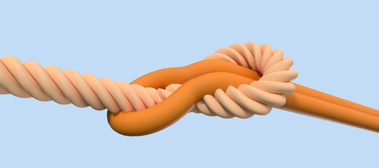
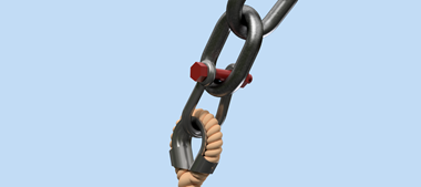
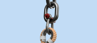
The Flexilink grid consists of a custom made round slings connected with Danline rope. To ensure that the rope retain its original MBL, and for the allowance to use 3 as a material factor, the correct method for connecting the parts together must be used.
The approved method for interconnection is a loop in a loop link, with a spliced eye on the rope.

Fiber ropes and thimbles
Thimbles must be installed on the ropes for protection against rubbing and wear. Ropes should not be linked directly to the shackles or other components, unless this is described in the mooring report, and if the required safety factor is taken into consideration when sizing the fiber ropes.
Splicing of ropes should always be performed by / approved by experienced personnel. There should always be minimum 4 tucs of each strand when a 3 stranded rope is used, and minimum 6 tucks when an 8 stranded rope is used. The thimble shall be secured against falling out by the use of PVC tape, mending twine or something similar (does not apply when using tube thimbles)
When the mooring is installed, the ropes must not be subjected to rubbing / wear / undue loads


Chains
Chains must always be installed with the use of shackles or other approved connection elements. Shackles shall always be connected to the short side of the chain link. Note that the chains have not been tested and approved for loadings on the long side.
When lowering the chains from a boat to the sea, the chains should not be exposed to side tension or twisting. When the chains have weight attached to them, it is important to release them at a steady rate to avoid twitching

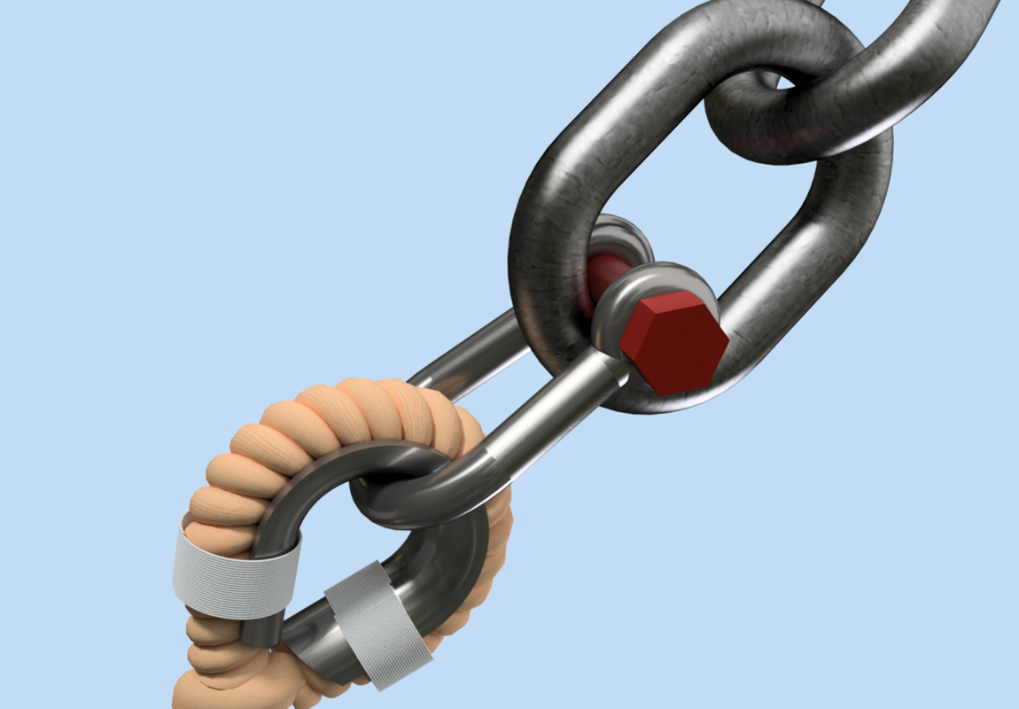
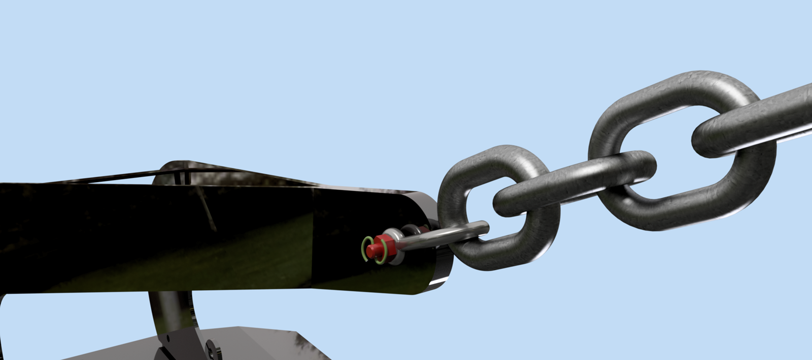
Shackles
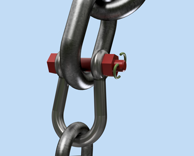
A mooring shackle consists of 3 separate parts - latch, bolt and nut. An accompanying locking pin is to be mounted next to the nut for double securing. One can only use the locking pin supplied with the shackle. Usage of the wrong locking pin can lead to faster corrosion and deterioration of the component. The nut must be tightened well. Although the latch is narrowed, it will not reduce the strength of the shackle.
The shackle can only be charged in the longitudinal direction - i.e. in the top of the latch and in the bolt.

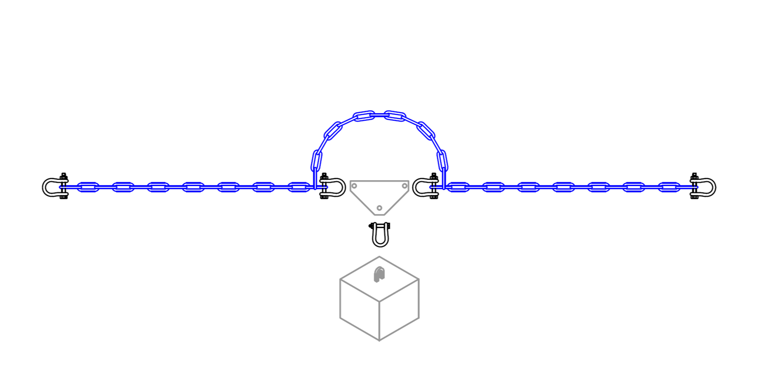
Connection plates
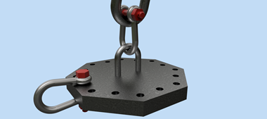
Connection plates supplied by Mørenot are constructed / designed for the shackle to be the last item mounted in the connection plate. Ensure that the bolt belonging to the shackle is placed down in the plate (nut and locking pin under the plate) to prevent the bolt from falling out if the shackle nut turns out / corrode
Different connection plates are supplied, but the principles are the same for all plates supplied by Mørenot.
There is an attachment in the middle of the plate, intended for attaching the buoys. Note that this attachment is not for attachment of the mooring lines, and should only be used for attaching the buoys

Buoys
Buoys shall be attached in the attachment point (bow) or to chains. The lifting eye should not be connected to the mooring. A shackle shall be used as the connector between the buoys and the mooring lines.
Anchors
Anchors shall be mounted with shackles and chains to the mooring lines. The anchors shall be placed at the position referred to in the mooring report. Once the anchor is in its’ right position, it should be pulled towards the floating collar with a force that equals the dimensioning force in the mooring line. If the anchor does not hold this load, it must be tested with a new anchor position, or one has to evaluate if the anchor type is compatible with the type of seabed.
Tests of the anchors holding power should be logged by the crew on the installation boat

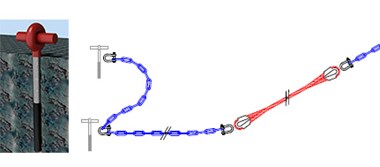
Rock bolts
Rock bolts for attaching mooring lines to the seabed are available in sizes from 32 to 45mm.
The diameter of the hole of each bolt are shown in the table below:
| Bolt, diameter | 32mm | 35mm | 38mm | 45mm |
| Hole, diameter | 36mm | 39mm | 42mm | 49mm |
Both pin bolts and bolts designed to be cemented can be used.
When installing pin bolts, the accompanying 6x70mm pin shall be used.
Make sure that the pin has penetrated the ground as required to expand sufficiently. The quality of the rock is essential for how the pin will work. The quality of the ground/ rock must be thoroughly evaluated before installation. If there is uncertainty about the structure and strength of the rock, resin anchored rock bolts should be considered. The installation must be done as described in the user manual for the resin.
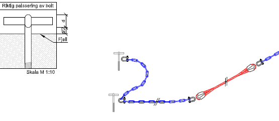
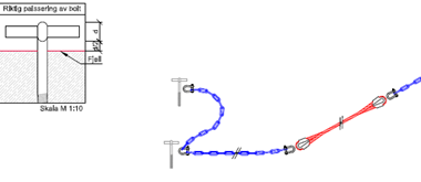
An eyebolt must be installed with the eye down.
A T-bolt shall not be installed with more than two times its own diameter from the rock to the T.
The bolt can be exposed for loadings no sooner than 24 hours after installation.

Weight / counterweight on anchors
Additional weight must be equipped if it is necessary to prevent uplift / vertical force on the anchors. Chains or concrete weights may be used as counterweight. Weights / chains that are installed to become part of the total strength of the mooring lines must be approved and dimensioned for this.

4.2 Weather conditions
Weather conditions such as current, ice, frost, etc. may have an impact on the quality of the mooring and the installation, and should therefore be evaluated during installation of the mooring. During installation the weather conditions must be constantly evaluated with regard to safety and quality of the different components.
Current conditions must be considered during deployment of anchors to ensure correct positioning.
4.3 Space requirements
It is recommended to have enough room and space to keep a good overview of all the components in the mooring system. It is also recommended to have a storage place in proximity to the site where the mooring shall be installed, to ensure more appropriate planning and efficiency during installation.
4.4 Additional equipment needs for installation
It is required to tighten the lock nut on the shackle with a wrench or a socket set. A pipe wrench may also be used.
Nuts and bolts for mooring shackles have the following dimensions:
| 28t MBL | 32mm |
| 40t MBL | 36mm |
| 60t MBL | 41mm |
| 90t MBL | 50mm |
Other additional tools: knife, tape, mending twine, lifting straps and locking ropes (for instance 24mm danline).
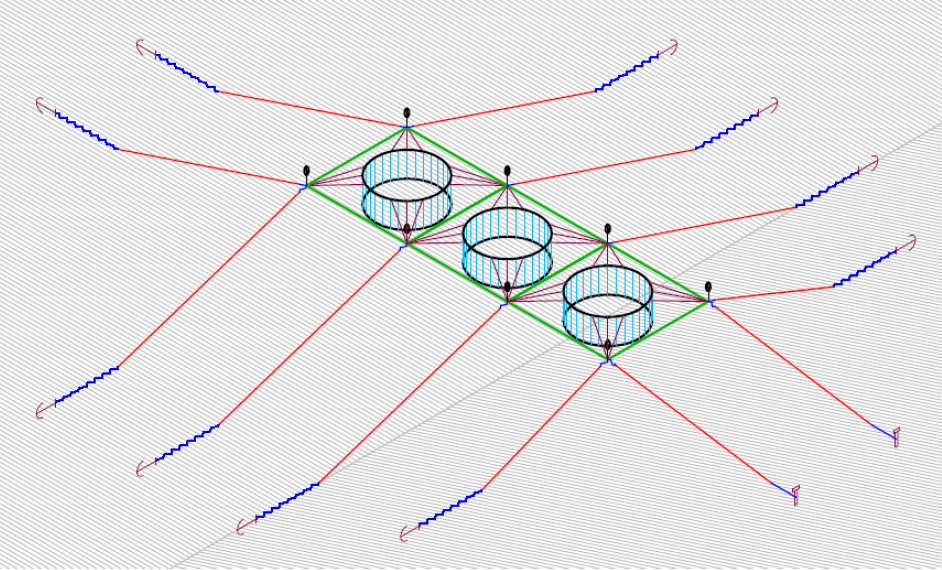
4.5 Illustrations for assembly, operation and maintenance
Mørenot Aquaculture AS provides mooring to the following cage constructions:
- Circular plastic rings
- Steel installations
- All types of barges and floating docks
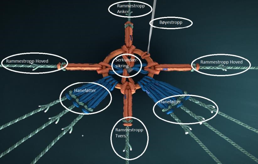
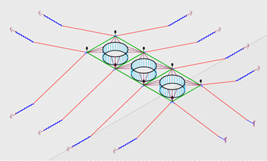
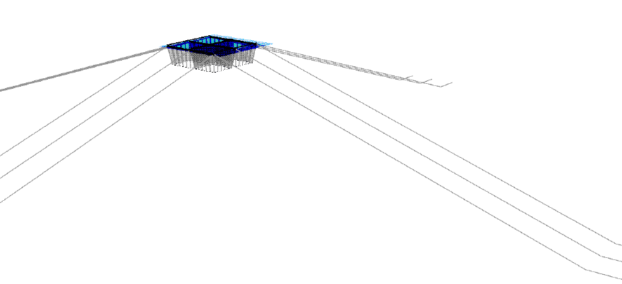
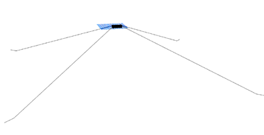
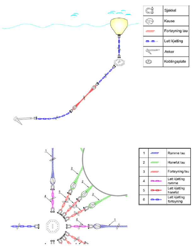
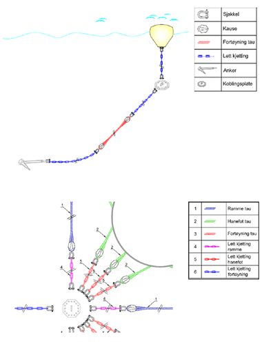
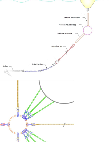
The following illustrations are examples on different configurations of mooring lines that can be used for all types of constructions. The chosen configuration must be based on an overall assessment of the requirements from the mooring analysis, the topography and characteristics of the bottom, lengths and angles of the mooring lines and requirements in the user manual for the floating collar.


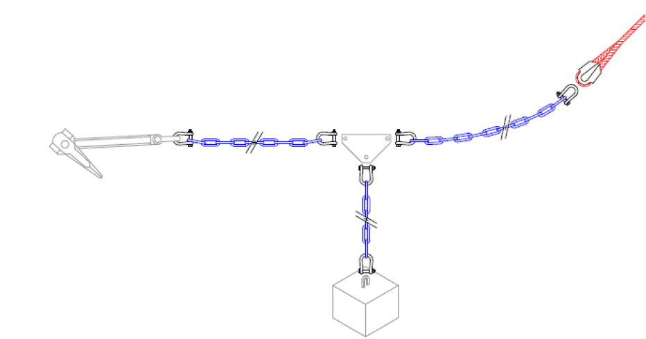


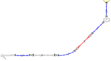
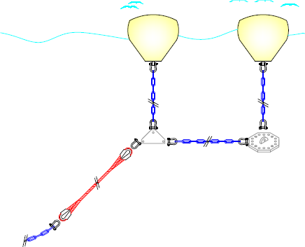

5. Interface with other main components
Construction parts for moorings should only be connected to other certified components. The attachment points on floating collars / barges must tolerate the loads imposed by the moorings. The loads / weight on the attachment points are specified in the mooring analysis, and the capacity for the attachment points are specified in the user manual for the cage.
Note that the components attached to the cages must be sized to fit the dimensions of the cages. Also note that the material of the components should not have any destructive effects on each other, e.g. corrosion.
6. Requirements for planned maintenance
The owner of the mooring system is required to perform maintenance as described in the user manual and the product certificates. This is to ensure that the individual components and the overall system are in their best possible conditions during their lifetime.
The lifespan of the individual components will vary according to the loads that they are subjected to during the operation period. Therefore, the owner / user of the system should perform a risk analyses based on the characteristics of each individual site. These risk analyses will be a supplement to the requirements of the user manual/ product certificates, to ensure that all eventualities are considered.
6.1 Risk analyses related to assembly and operation of the mooring system
The owner of the mooring system is required to conduct a risk assessment that covers both installation and operation of the mooring system. In this assessment all elements related to the specific site and fish farm shall be taken into account. The risk assessment should be based on a systematic risk analysis.
The risk assessment can, and should, lead to changes in the planned maintenance programs specified in the user manual. One cannot make changes that reduce the number of inspections or reduce the number of objects to be inspected. Individual risk assessments cannot result in increased lifespan of the individual components beyond what is specified in the user manual or in the product certificates.
For instance; bridle attachments that only consists of ropes will be more susceptible to sun and propeller damage than bridles with chains at the upper few meters towards the cage, and should be inspected more often. Also; special environmental conditions should be considered in the risk assessment.
The risk analysis should lead to a detailed inspection program.
6.2 Inspection programs
Inspection intervals and scope of inspections vary according to the types of mooring systems installed at the site. Due to varying risk, inspection programs are differentiated for the following types of mooring system:
- Mooring grids with connection plates with 8 holes
- Mooring grids with connection plates with 12-16 holes
- Mooring grids with Flexilink
- Mooring for barges and steel constructions
Inspection programs are divided into 4 different types:
- Periodical inspection - should be performed at a fixed frequency and at fixed checkpoints.
- Main inspection - should be performed at a fixed frequency or following major changes
- Incident-initiated inspection – should be performed after events that may have led to damages or significant weakening of the moorings.
- Functionality test / inspection - should be performed if it is considered necessary to test the capacity of one or more components in the system.
For all types of mooring systems there is a requirement in the Nytek regulation to conduct an inspection with ROV or divers after installation and before fish are put out.
6.3 Periodical inspection
Those responsible for the daily operation, as well as external personnel, may perform the periodical inspection. The performed inspection shall be entered into a log, or otherwise documented, and deviations should be corrected as soon as possible.
| Mooring | Frequency | Checkpoint | Specifications | How |
|---|---|---|---|---|
| Grids with connection plates, 8 holes | Every three months | All the connection plates and all parts connected to them (shackles, chains…)
Grid ropes | Check for:
Missing splint in the bolt Loose nut on the bolt Wear on the rope close to the connecting point Corrosion Fatigue in steel components | Diver, ROV or camera
Connection plates can also be lifted to the surface for inspection, using crane or winch |
| Grids with connection plates, 12- 16 holes | Every nine months | All the connection plates and all parts connected to them (shackles, chains…)
Grid ropes | Check for: Missing splint in the bolt Loose nut on the bolt Wear on the rope close to the connecting point Corrosion Fatigue in steel components | Diver, ROV or camera Connection plates can also be lifted to the surface for inspection, using crane or winch |
| Grids with Flexilink slings | Every 12 months | All main fiber slings, and all slings attached to the main fiber sling.
Grid ropes | Check for: Wear or damage to the fiber sling and ropes. A blue color appearing on the main fiber sling indicates wear. If the cover is worn down until the white color, the main fiber sling must be replaced | Diver, ROV or camera
The connection point may also be lifted to the surface for inspection, using crane or winch |
| Anchor lines | Every 12 months | The upper part of all anchor lines | Check:
The attachments to the connecting points
If any of the lines are particularly slack or tight. If there are deviations, the entire line must be inspected | Diver, ROV or camera |
| Bridles / attachments to the cages / barge | Every 12 months | All attachments to the cages / barge | Check: The attachments to the connecting points and to the cages | Diver, ROV or camera Connection plates |
6.4 Main inspection
The main inspection is a full review of the mooring system. It is an advantage if the inspection coincide with the fallowing period of the site. The inspection shall be performed by personnel with documented expertise and experience within this operation. The inspection shall be documented in a report and with photos showing that all the lines have been inspected. All deviations must be recorded and corrected as soon as possible.
If any of the components to be inspected are fouled, they must be cleaned before inspection.
| Mooring | Frequency | Checkpoint | Specifications | How |
|---|---|---|---|---|
| Grids with connection plates, 8 holes | Every four years | All the connection plates and all parts connected to them (shackles, chains…)
Grid ropes | Check for:
Missing splint in the bolt. Loose nut on the bolt
Wear on the rope close to the connecting point Corrosion Fatigue in steel components. | Diver, ROV or camera
Connection plates can also be lifted to the surface for inspection, using crane or winch |
| Grids with connection plates, 12- 16 holes | Every four years | All the connection plates and all parts connected to them (shackles, chains…)
Grid ropes | Check for: Missing splint in the bolt. Loose nut on the bolt Wear on the rope close to the connecting point Corrosion Fatigue in steel components. | Diver, ROV or camera Connection plates can also be lifted to the surface for inspection, using crane or winch |
| Grids with Flexilink slings | Every four years | All main fiber slings, and all slings attached to the main fiber sling Grid ropes | Check for: Wear or damage to the fiber sling and rope. A blue color appearing on the main fiber sling indicates wear. If the cover is worn down until the white color, the main fiber sling must be replaced | Diver, ROV or camera The connecting point may also be lifted to the surface forinspection, using crane or winch. |
| Anchor lines | Every four years | All anchor lines
The entire line must be inspected | Check:
The attachments to the connecting points
If any of the lines are particularly slack or tight. If there are deviations, the entire line must be inspected Anchors and rock bolts, especially for contact between ropes and the bottom | Diver, ROV or camera |
| Bridles / attachments to the cages / barge | Every four years | All attachments to the cages / barge | Check:
The attachments to the connecting points and to the barges
Check the full length of the bridle for wear and damage caused by boats etc. | Diver, ROV or camera Connection plates can also be lifted to the surface for inspection, using crane or winch |
6.5 Incident - initiated inspection
Inspections should be made after the occurrence of incidents / events that might have caused damage to the mooring system or parts of it. Examples of events that should trigger inspections are:
- prolonged periods with high waves and / or current
- Short periods of extreme weather
- Suspicion that an anchor line has moved – change of the fish farms position
- Collision with boats
- Notification of suspected defects on components in the mooring system
The inspection shall be performed by experienced personnel - if necessary by ROV or divers. The inspections must be documented, and all deviations must be recorded and corrected as soon as possible.
6.6 Functionality test / inspection
Functionality inspections should be performed if one suspects that a single, or several components, do not hold the necessary capacity. Examples of this are:
- The chosen anchor type is not optimal for the bottom type and topography
- Missing or incorrect documentation of breaking loads
- Suspected defects on individual components
Testing of the components function can be done at the site, or at suitable test facilities. Mørenot Aquaculture AS must be contacted to make sure that proper procedures are followed when the tests are performed.
6.7 Lifespan and replacement rates
Based on empirical data, uncertainties related to the corrosion rate, UV exposure and abrasion, all mooring components supplied by Mørenot Aquaculture AS are said to have a general lifetime of 10 years. This lifetime can be reduced based on analysis of fatigue or based on risk assessments conducted by the fish farmers.
The lifespan can be prolonged if the components are tested in accordance with approved procedures. Mørenot Aquaculture AS can be contacted for details about this.
| Component | Lifespan | Criteria for prolonged lifespan | Criteria for replacements (one or more criteria) |
|---|---|---|---|
| Standard ropes, danline quality | 10 years | Selected lines are tested in a test bench. Reduction of breaking loads are compared with requirements in the mooring analysis | 30 % reduction in MBL Visible wear |
| Flexilink | 10 years | The most deprived connection fiber sling is tested in a test bench | 30 % reduction in MBL Wear on both fiber covers making the polyester visible (white color showing) |
| Flexilink anchor line slings | 10 years | The most deprived sling on the anchor lines is tested in a test bench | 30 % reduction in MBL Wear on both fiber covers making the polyester visible (white color showing) |
| Flexilink bridle slings | 10 years | The most deprived sling on the bridles is tested in a test bench | 30 % reduction in MBL Wear on both fiber covers making the polyester visible (white color showing) |
| Galvanized chain G70 Galvanized shackle Galvanized connection loop | Five years if used in the upper part of the water column
10 years if used deeper than 15 m below the surface
Note that the fatigue analysis affects the estimated lifespan | An 0.4 mm reduction in the thickness of the steel per year is assumed. New breaking load (MBL) is calculated based on remaining size and quality | 30 % reduction in MBL Damage or corrosion pits Deformation |
| Black chains G40 (bottom chains) | 10 years, or in accordance with the fatigue analysis | An 0.4 mm reduction in the thickness of the steel per year is assumed. New breaking load (MBL) is calculated based on remaining size and quality | 30 % reduction in MBL Damage or corrosion pits Deformation |
| Connection plates, steel | 10 years, or in accordance with the fatigue analysis | Measurement of remaining thickness and size of the holes. New breaking load (MBL) is calculated based on remaining size and quality | 30 % reduction in MBL Damage or corrosion pits Deformation |
| Shackle | Five years if used in the upper part of the water column 10 years if used deeper than 15 m below the surface | An 0.4 mm reduction in the thickness of the steel per year is assumed. The exact remaining thickness may also be measured. New breaking load (MBL) is calculated based on remaining size and quality | 30 % reduction in MBL Damage or corrosion pits Deformation |
| Rock bolt | Five years if used in the upper part of the water column 10 years if used deeper than 15 m below the surface | ROV / diver inspection showing no deviations
Test of holding power compared with the designed loads | 30 % reduction in MBL Damage or corrosion pits Deformation |
| Anchors | 10 years | ROV / diver inspection showing no deviations
Test of holding power compared with the designed loads Remaining thickness for the attachment | 30 % reduction in MBL Damage or corrosion pits Deformation |